Solving common challenges relating to aggressive, abrasive, and toxic media
The MCG Advanced Materials Division is a specialist fluorocarbon processor, chemical equipment supplier, and leading manufacturer and supplier of high-quality engineering plastics in South Africa for all heat, wear and corrosive applications.
Advanced engineering plastics provide you and your application with high dimensional stability, superior release, elevated thermal stability, and more. These materials are lightweight and mechanically tough – they can withstand rigorous operating conditions while meeting demanding performance requirements and tight tolerances. Plus, our in-house machining capabilities mean we can manufacture your engineering plastic components to precision for any application.
- Exceptional impact and abrasion resistance
- Superior wear resistance
- Low friction properties
- Excellent sliding properties due to highly homogenous and waxy surfaces
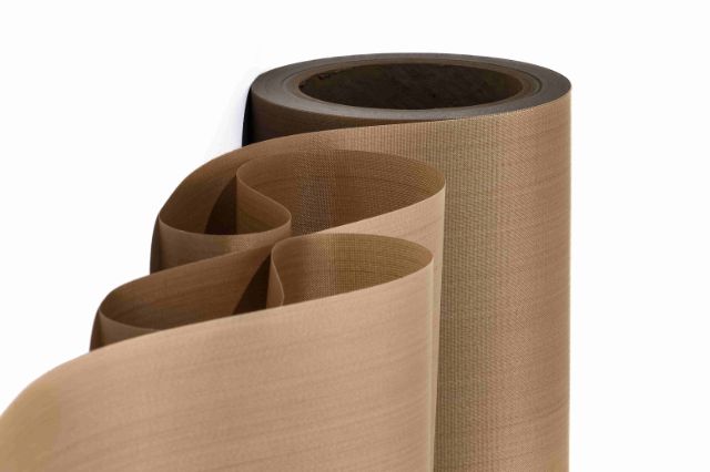
Versiv™ PTFE coated fabrics & belts
If your application demands reliable release, high wear resistance, or thermal stability, choose Versiv™ non-stick solutions with PTFE coating. These products meet demanding requirements, and they can also withstand rigorous operating conditions.
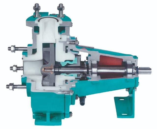
WERNERT pumps
Operating with aggressive, abrasive, or toxic media? WERNERT chemical pumps are designed with extreme operating conditions in mind, made from high-performance, non-metallic materials supported by cast steel.
TIVAR™ UHMW-PE low-friction linings
For common bulk flow challenges like caking, bridging, rat-holing, and bottlenecking, try our low-friction materials and lining solutions. Our extensive range of TIVAR™ UHMW-PE liners exhibit exceptional impact & abrasion resistance properties.
KEYLON™ PTFE stock shapes
With excellent resistance to heat and chemicals as well as an ultra-low coefficient of friction, KEYLON™ PTFE is an excellent choice for high wear applications. Explore the forms and sizes we manufacture.

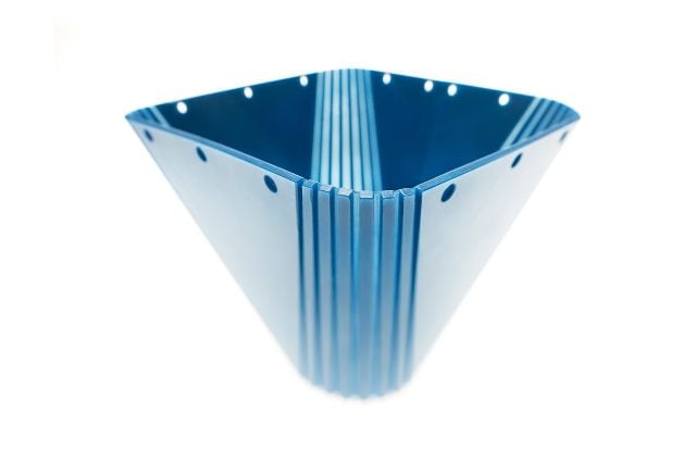
Dewatering elements
Our TIVAR™ UHMW-PE thermoplastic solutions are designed for use in the most extreme operating conditions. Developed over many years of specialized international expertise, our dewatering elements provide you with superior wear resistance and excellent sliding properties due to highly homogenous and waxy surfaces.
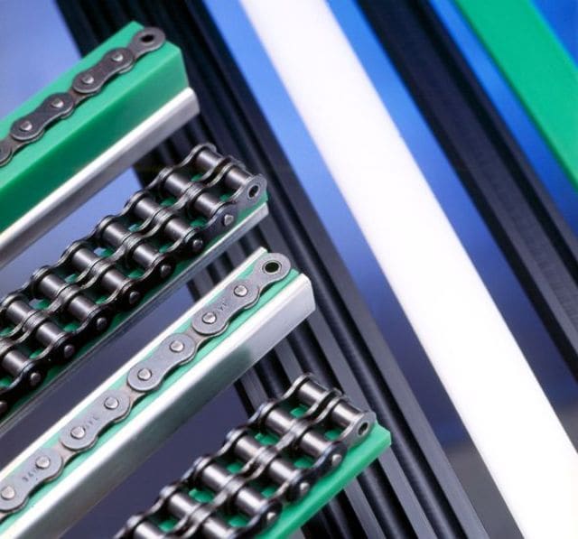
Wearstrips & profiles
From unit material handling in food processing and semiconductor applications, to medical components, transportation, and water treatment, our custom and flexible wearstrip solutions help you improve the service life, performance, and safety of your application. We also offer chain guide shapes, corner wear bends, and sliding supports and guides.
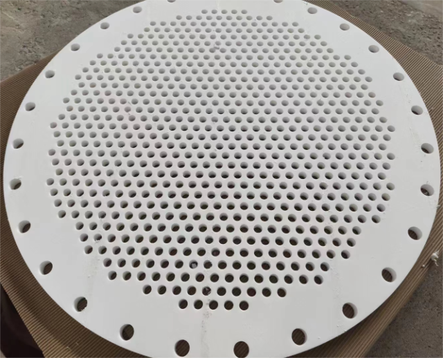
Machined components
Our in-house machining capabilities mean we can machine your engineering plastic components to precision for any application. We don’t just help you find the right materials solution; we also manufacture your parts efficiently and cost-effectively – even if your application involves complex geometries and tight tolerances.
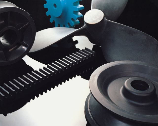
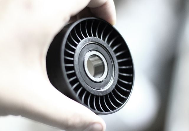
Cast nylon products
For materials handling applications, our Nylatron™ solutions provide you with greater capacities, extended service life, and cleaner discharges. Our cast products are lightweight and mechanically tough, making them ideal for your bearings, sprockets, and other lifting equipment.
Interested in replacing a component material with a high-performance engineering plastic? Looking to make changes or improvements to an existing application? Have an ambitious idea, but not sure of the next steps?
Get started with our industry-leading experts today.